Physical Address
304 North Cardinal St.
Dorchester Center, MA 02124
Physical Address
304 North Cardinal St.
Dorchester Center, MA 02124

Everything about electronics
Everything about electronics

As we know
that Arduino contains ADC channels of 10-bit resolution. But if we require the
measurement to be done with higher resolution then we can opt for the ADS1115
module. It contains 16 bit ADC with 4 channels and communicates with I2C
protocol. Out of 16 bits, 15 bits are
used for the measurement and the 16th bit is for the polarity. So we
can measure the negative values from this also.
Setting the gain
In this, we can set various resolution as per level of our input signal. we just have to use below code to st the resolution.
Gain select command Gain Voltage Range Resolution
ADS1015 ADS1115
ads.setGain(GAIN_TWOTHIRDS); // 2/3x gain +/- 6.144V 1 bit = 3mV 0.1875mV
ads.setGain(GAIN_ONE); // 1x gain +/- 4.096V 1 bit = 2mV 0.125mV
ads.setGain(GAIN_TWO); // 2x gain +/- 2.048V 1 bit = 1mV 0.0625mV
ads.setGain(GAIN_FOUR); // 4x gain +/- 1.024V 1 bit = 0.5mV 0.03125mV
ads.setGain(GAIN_EIGHT); // 8x gain +/- 0.512V 1 bit = 0.25mV 0.015625mV
ads.setGain(GAIN_SIXTEEN); // 16x gain +/- 0.256V 1 bit = 0.125mV 0.0078125mV
The default gai is the 2/3x gain.
(adsbygoogle = window.adsbygoogle || []).push({});
Image
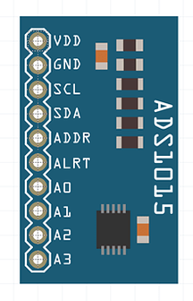
The module
looks like the below image.
The code is
very simple and uses the Adafruit ADS1115 library which can be downloaded from
this link- https://github.com/adafruit/Adafruit_ADS1X15
(adsbygoogle = window.adsbygoogle || []).push({});
Connections
The
connections are very simple and are made through the pins available on board.

But to get
the data we just need to connect the below connections
Vdd:- To the
device supply
GND:- Device
ground
SCL:- SCL
pin of Arduino
SDA:- SDA
pin of Arduino
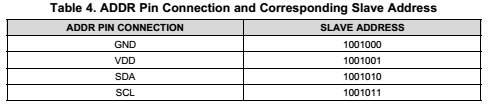
ADDR:- This
pin defines the address for the device for I2C communication. And if we are
using only one chip then just connect this to ground. Different addresses for
different connections are shown below as
A0 to A3:-
To analog input lines
(adsbygoogle = window.adsbygoogle || []).push({});
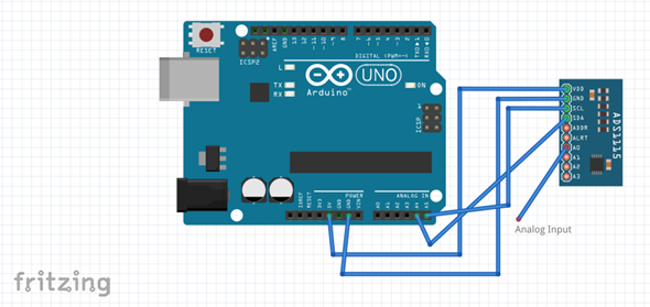
Circuit Connections
The sample
connections are shown below.
Example Code
Below is the
example code
#include
<Wire.h>
#include
<Adafruit_ADS1015.h>
//
Adafruit_ADS1115 ads; /* Use this for
the 16-bit version */
Adafruit_ADS1015
ads; /* Use thi for the 12-bit
version */
void
setup(void)
{
Serial.begin(9600);
Serial.println(“Hello!”);
Serial.println(“Getting single-ended
readings from AIN0..3”);
Serial.println(“ADC Range: +/- 6.144V (1
bit = 3mV/ADS1015, 0.1875mV/ADS1115)”);
// The ADC input range (or gain) can be
changed via the following
// functions, but be careful never to exceed
VDD +0.3V max, or to
// exceed the upper and lower limits if you
adjust the input range!
// Setting these values incorrectly may
destroy your ADC!
//
ADS1015 ADS1115
//
——- ——-
// ads.setGain(GAIN_TWOTHIRDS); // 2/3x gain +/- 6.144V 1 bit = 3mV 0.1875mV (default)
// ads.setGain(GAIN_ONE); // 1x gain +/- 4.096V
1 bit = 2mV 0.125mV
// ads.setGain(GAIN_TWO); // 2x gain +/- 2.048V
1 bit = 1mV 0.0625mV
// ads.setGain(GAIN_FOUR); // 4x gain +/- 1.024V
1 bit = 0.5mV 0.03125mV
// ads.setGain(GAIN_EIGHT); // 8x gain +/- 0.512V
1 bit = 0.25mV 0.015625mV
// ads.setGain(GAIN_SIXTEEN); // 16x gain
+/- 0.256V 1 bit = 0.125mV 0.0078125mV
ads.begin();
}
void
loop(void)
{
int16_t adc0, adc1, adc2, adc3;
adc0 = ads.readADC_SingleEnded(0);
adc1 = ads.readADC_SingleEnded(1);
adc2 = ads.readADC_SingleEnded(2);
adc3 = ads.readADC_SingleEnded(3);
Serial.print(“AIN0: “); Serial.println(adc0);
Serial.print(“AIN1: “);
Serial.println(adc1);
Serial.print(“AIN2: “);
Serial.println(adc2);
Serial.print(“AIN3: “);
Serial.println(adc3);
Serial.println(” “);
delay(1000);
}
The datasheet for this can be downloaded from this link
http://www.ti.com/lit/gpn/ads1115
Try the
module and comment your observations below.
Aniruddh Sharma
Ani-Lab
(adsbygoogle = window.adsbygoogle || []).push({});
