Physical Address
304 North Cardinal St.
Dorchester Center, MA 02124
Physical Address
304 North Cardinal St.
Dorchester Center, MA 02124

Everything about electronics
Everything about electronics
So how do we go about programming something like this if we can’t connect it to our computer using USB? We use what’s called a USB-Serial converter.
When we use the term ‘serial’ for these converters we are referring to TTL serial data compatible with the UART ports found on almost every chip (the Atmega328 has one UART port, the mega2560 has four). Before we go on, perhaps a term clarification is in order:
So as you can see, just because a computer has a USB port, doesn’t mean that you can just take the data lines and tack them onto a UART port, proper conversion must take place between the USB data protocol, and UART protocols. Some microcontroller chips, such as the Atmega16u2 have a built-in USB port (denoted by the ‘u’) which means that they have the hardware required to support USB communication built into them. However, the ones that don’t will usually have a UART port which we can use to program the board (providing the bootloader allows for this). The UART port on a board can be located by the pins labeled TX and RX. The TX pin is the transmit pin used to send data from the device to another device and the RX pin is the receive pin used to receive data from another device.
Fortunately, there exist plenty of devices designed to bridge this barrier: USB-Serial converters. They do exactly as the name implies, connect to the USB port of your computer, and convert the USB data into data compatible with a UART port which allows you to communicate to and from your device, to your computer. Chips also contain what is known as a ‘bootloader’ and this is just a small piece of code which tells your device what to do when it boots up. Now most chips on Arduino boards have a special bootloader on board which allows them to be programmed via the TX and RX pins, so we can also program our Arduino board using a USB-Serial converter. Sometimes these converters are also known as USB-TTL converters or USB FTDI converters. FTDI is a company who produces the most well-known USB-Serial converter chips and hence many converters are known simply as FTDI cables or converters.
(adsbygoogle = window.adsbygoogle || []).push({});
With so many different options to choose from, we’ve selected a couple of our favorites to suit every project:
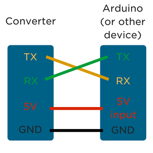
Connecting up the USB-Serial converter is pretty straight forward. You’ll want to connect the 5V pin to the 5V input of your board to power it (or you can power it separately and only connect the ground). Then the TX pin on your converter to the RX pin on your board, and the RX pin on your converter to the TX pin on your board. If this sounds a bit confusing and backward, remember that TX is outgoing data, and RX is inbound data, so the TX pin on the converter is sending data from the USB port, and the RX pin on the Arduino is receiving data, so you want those to be connected, and vice-versa. If you’re using the Arduino USB 2 Serial converter, you can take advantage of the external reset pin, check out the link above for wiring info.
![]() We’re going to run through using any of the boards above to program and communicate using the UART port on an Arduino, however, the method is going to be the same for any board with a UART port or has a bootloader capable of being programmed via the UART port. But first, we need to install the FTDI drivers which allow the converter board (with the FTDI chip on board) to show up as COM port. To download the drivers and get them setup, check out Sparkfun’s fantastic guide on setting installing FTDI drivers.
We’re going to run through using any of the boards above to program and communicate using the UART port on an Arduino, however, the method is going to be the same for any board with a UART port or has a bootloader capable of being programmed via the UART port. But first, we need to install the FTDI drivers which allow the converter board (with the FTDI chip on board) to show up as COM port. To download the drivers and get them setup, check out Sparkfun’s fantastic guide on setting installing FTDI drivers.
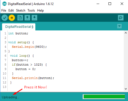
Now let’s take a look at sending data to our serial monitor using the converter. Open up Arduino IDE and copy the following code into it:
int button;

void setup() {
  Serial.begin(9600);
}
 void loop() {
  button++;
  if(button > 1023) {
    button = 0;
  }
  Serial.println(button);
 }
(adsbygoogle = window.adsbygoogle || []).push({});
This is a super simple program that increments a variable by one, then prints the value of that variable to the serial monitor. The communication from our board to the computer is happening via the TX/RX lines to our USB-Serial converter so we can tell if it’s working or not. Now after installing the FTDI drivers, you should see your converter come up as a COM port. Target it, and ensure that you have the correct board type selected. Now something to take note of here is that the reset pin is required to program the Arduino board. In order for the Atmega328 to be programmed via the UART port, the reset pin must be held low and then released to high at a certain point during the upload process. The Arduino brand USB-Serial converter has a specific pin for this which you can connect to the reset pin, however, for the other boards, you will need to hold the reset button by hand. Here’s the correct sequence:
Success! Your board should now be successfully programmed using the USB-Serial converter! You can now leave it connected as is to allow serial communication between your board and the computer, and if you open up the serial monitor, you can see the count variable incrementing.
And that ladies and gentlemen is how you can use an FTDI board, otherwise known as a USB-Serial converter to program and communicate via the UART port on your board. Remember that not all chips can be programmed via UART (the Arduino bootloader makes this possible) but all chips can communicate via UART, for example, you could use a USB-Serial converter to allow a Raspberry Pi to communicate data to your computer using its serial port.
(adsbygoogle = window.adsbygoogle || []).push({});